

Image Processor
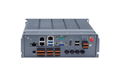
The CK-9035-IO industrial computer adopts a fanless and integrated thermal design, providing shock resistance and dust protection. It features a compact and flexible appearance with ultimate performance.Specifically developed for machine vision industrial applications, it boasts high stability, low cost and fast response. It is suitable for scenarios such as robot guidance and tracking, positioning, measurement and recognition.
Specifications
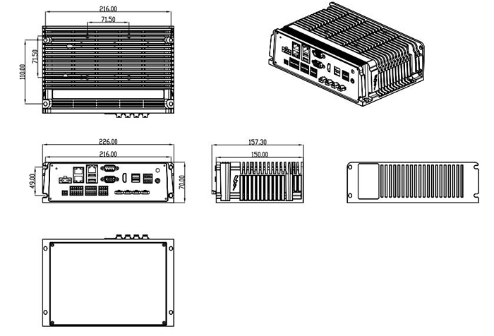
Dimensions
Downloads
Product Specifications
| Category | Item | Specification |
|---|---|---|
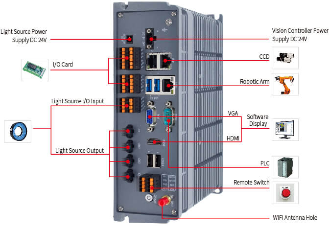
| Basic Functions | Ethernet Port | 3* Gigabit Ethernet Ports (1RTL 8111H, 2Intel i226V, 2 ports support PoE) |
| Display Interfaces | 1″VGA+1*HDMI | |
| Serial Port | 2RS-232 + 1RS-485 | |
| USB | 2USB 3.0 + 4USB 2.0 (2 ports built-in) | |
| GPIO | 8DI + 8DO | |
| Light Source | 4* Light Source Interfaces, rated current per channel: 1A | |
| TRIG | 4* Light Source Trigger Interfaces | |
| WIFI | WIFI supported by default | |
| Remote Switch | 1* Remote Extension Switch | |
| Operating Characteristics | Power Supply | DC IN 24V |
| Power Consumption | Typical: 9.28W; Maximum: 16.32W | |
| Operating Temperature | 0°C ~ +60°C | |
| Storage Temperature | -40°C ~ +85°C | |
| Operating Humidity | 5% ~ 90% (non-condensing) | |
| Storage Humidity | 5% ~ 90% (non-condensing) | |
| Physical Specifications | Overall Dimensions | 226mm157.3mm70mm (LWH) |
| Net Weight | Approx. 2.07 Kg (excluding accessories and packaging) |
Interface Diagram
Interface Definition
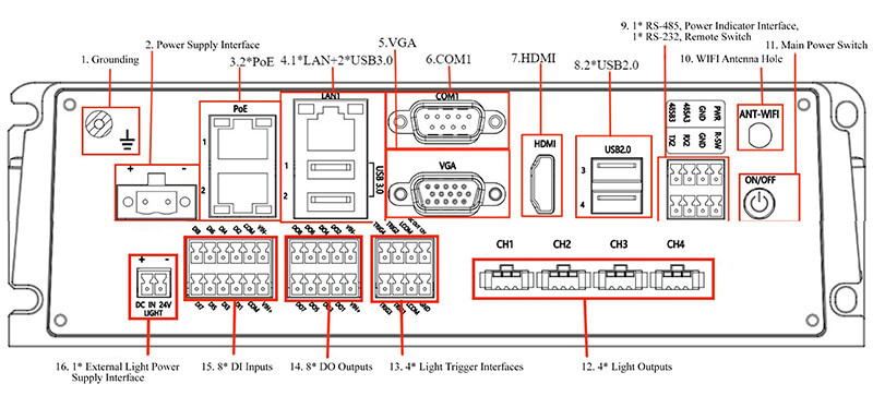
| No. | Silkscreen | Function | Interface Type & Description |
|---|---|---|---|
| 1 | Ground Symbol | Grounding | Grounding hole mark, for M3*8 combination screw |
| 2 | DC IN 24V | 1* Power Supply Interface | 1 x 2-Pin 5.08mm pitch black Phoenix terminal |
| 3 | PoE1/2 | 2* PoE Ports | 1 x RJ45 dual-layer port |
| 4 | LAN/USB3.0 | 1* LAN + 2* USB3.0 Ports | 1 x RJ45 port and 2 x USB3.0 ports |
| 5 | VGA | 1* VGA Display Interface | 1 x standard DB-15 female connector |
| 6 | COM1 | 1* RS-232 Port | 1 x standard DB-9 male connector |
| 7 | HDMI | 1* HDMI Display Interface | 1 x standard HDMI port |
| 8 | USB2.0 | 2* USB2.0 Ports | 1 x dual-layer USB port |
| 9 | RX2 TX2 | 1* RS-232 Port | System serial port: COM2 |
| 485A3 485B3 | 1* RS-485 Port | System serial port: COM3 | |
| PWR GND | 1* Power Indicator Interface | PWR and GND form the power indicator interface | |
| R-SW GND | 1* Remote Switch Interface | R-SW and GND form the remote switch interface | |
| 10 | ANT-WIFI | 1* WIFI Antenna Hole | 1 x φ6.5mm round hole |
| 11 | ON/OFF | 1* Main Power Switch | 1 x round switch socket |
| 12 | CH1-CH4 | 4* Light Output | Rated current per channel: 1A |
| 13 | DC OUT 12V GND | 12V Output | 1 x 2*4-Pin 3.5mm pitch black Phoenix terminal |
| LCOM | Light Trigger Common Port | 1 x 2*4-Pin 3.5mm pitch black Phoenix terminal | |
| TRIG1-TRIG4 | 4* Light Trigger | 1 x 2*4-Pin 3.5mm pitch black Phoenix terminal | |
| 14 | VIN+ VIN- | DO Power Supply Interface | 1 x 2*5-Pin 3.5mm pitch black Phoenix terminal |
| DO1 – DO8 | 8* DO Output | 1 x 2*5-Pin 3.5mm pitch black Phoenix terminal | |
| 15 | VIN+ VIN- | DI Power Supply Interface | 1 x 2*6-Pin 3.5mm pitch black Phoenix terminal |
| COM | DI Input Common Port | 1 x 2*6-Pin 3.5mm pitch black Phoenix terminal | |
| DI1 – DI8 | 8* DI Input | 1 x 2*6-Pin 3.5mm pitch black Phoenix terminal | |
| 16 | DC IN 24V LIGHT | 1* External Light Power Supply Interface | 1 x 1*2-Pin 3.5mm pitch black Phoenix terminal |
Top