A New Paradigm for Flexible Feeding in the Smart Manufacturing Era
Abstract
In recent years, Flexible Vibrating Disk has rapidly penetrated automated production lines in 3C electronics, automotive parts, medical devices and other fields thanks to its advantages of multi-material compatibility and fast changeover. However, without highly reliable machine vision support, the potential of flexible feeding systems will be greatly compromised. This paper deeply analyzes the working principle and core challenges of Flexible Vibrating Disk, systematically elaborates the key role of CKVision Image Processor in feature detection, pose recognition and real-time feedback control, and reveals the advantages of capacity improvement, changeover efficiency and quality assurance brought by their in-depth integration through typical cases. Finally, the future development trends are prospected.
1. Introduction: A Feeding Revolution Under the Wave of Flexible Manufacturing
Against the backdrop of ever-shortening iteration cycles of consumer electronics and surging demand for personalized customization, the drawbacks of traditional Rigid Bowl Feeder, which relies on specific chute tracks and requires hours of changeover time, have become increasingly prominent. A modern SMT line often needs to handle dozens of material specifications simultaneously, and the cost and management complexity of customized bowls for a single material have become the biggest obstacles to improving flexibility. The emergence of Flexible Vibrating Disk is a direct response to this pain point.
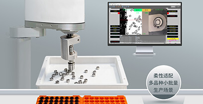
Flexible Vibrating Disk replaces fixed tracks with planar electromagnetic excitation or piezoelectric actuation, and mechanical guidance with high-speed cameras and image processors, realizing a fundamental shift from “physical constraints” to “vision guidance”. Nevertheless, the core competitiveness of this system ultimately lies in the perception and decision-making capabilities of the image processor. It must achieve precise positioning, pose judgment and pick-up guidance of parts under extreme working conditions such as high speed, strong vibration and complex backgrounds. Industrial image processors represented by CKVision have become an indispensable “brain” in Flexible Vibrating Disk systems by virtue of their deeply integrated vision algorithms and open interface ecosystem.
This paper comprehensively explains the complete picture of the collaborative operation of Flexible Vibrating Disk and CKVision Image Processor from three dimensions: technical principle, system architecture and practical cases, providing references for automation engineers, production line planners and smart manufacturing decision-makers.
2. Working Principle and Technical Characteristics of Flexible Vibrating Disk
2.1 Core Driving Mechanism
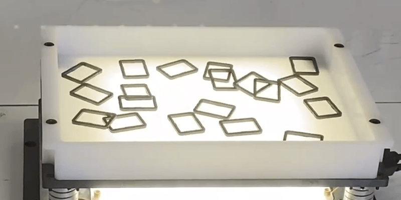
The disk surface of Flexible Vibrating Disk is usually a flat platform made of stainless steel or epoxy fiber, with multiple groups of independently controllable electromagnetic excitation units or piezoelectric ceramic arrays arranged underneath. By differentially controlling the phase, frequency and amplitude of each excitation unit, the system can generate standing waves or traveling waves in any direction on the disk surface, thereby driving parts to move, rotate or stop along a specified path. This “software-defined material conveying path” enables the same equipment to be compatible with materials of different shapes and weights without any mechanical modification.
Common excitation solutions include: full-plane array type (up to dozens of independent excitation points with the highest control precision), zoned type (dividing the disk surface into several independently controlled areas with lower cost) and single-point high-frequency type (suitable for small and lightweight parts). Different solutions make trade-offs between part compatibility range, conveying speed and system cost, which need to be selected according to specific application scenarios.
2.2 Necessity of Visual Closed-Loop Control
Different from traditional vibrating feeders that rely on fixed tracks to filter directions, the poses of parts on the Flexible Vibrating Disk are completely random. The image processor needs to detect the position coordinates (X, Y), rotation angle (θ) and front/back status of each part in real time, then calculate the optimal excitation strategy through algorithms to guide parts to move to the target pose range of the pick-up area, and finally cooperate with robots or pneumatic pick-up mechanisms to complete picking.
This closed-loop control imposes extremely stringent requirements on the image processor: detection delay must be less than 50ms (to match high-speed pick-up beats), high repeat positioning accuracy must be maintained under vibration and lighting changes, multi-part simultaneous tracking must be supported, and real-time data exchange with the vibration controller must be enabled.
2.3 Major Challenges
- Part diversity: The same production line may need to handle parts with a spanning specification range from 0402 chip components to M8 bolts, making the generalization ability of vision algorithms crucial.
- Reflective and transparent materials: The surface optical characteristics of metal fasteners, optical lenses, transparent plastic covers and other materials are extremely complex, posing dual challenges to lighting design and image algorithms.
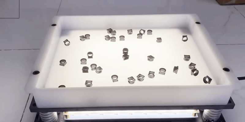
- Vibration blur: Continuous vibration of the disk causes slight displacement of parts during exposure, requiring the cooperation of strobe light sources and extremely short exposure times to obtain clear images.
- Real-time requirements: The end-to-end delay of the entire detection-decision-control loop directly determines the upper limit of production line beats, and any processing bottleneck will cause efficiency loss.
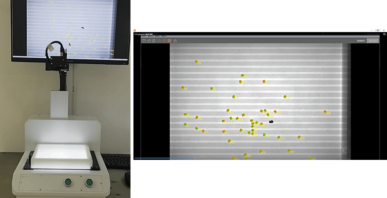
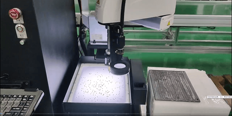
3. Core Technical Capabilities of CKVision Image Processor
3.1 Overview of Hardware Architecture
CKVision Image Processor is based on a high-performance embedded computing platform, integrating an FPGA preprocessing unit and a multi-core CPU/GPU co-processing architecture. The FPGA undertakes time-delay-sensitive tasks such as image acquisition synchronization, strobe control signal output and primary filtering, while the CPU/GPU is responsible for feature extraction, deep learning inference and result output. This heterogeneous computing architecture ensures that the system can run complex neural network models while maintaining millisecond-level response.
In terms of interfaces, CKVision Image Processor natively supports GigE Vision, Camera Link and USB3 Vision camera standards, and can be flexibly matched with industrial cameras of different resolutions and frame rates. The I/O interface provides multiple configurable digital I/Os to directly drive the strobe light controller, eliminating synchronization jitter caused by additional controllers. Ethernet and EtherCAT/PROFINET fieldbus interfaces ensure low-latency data exchange with vibration controllers and upper-layer MES systems.
3.2 Vision Algorithm System
The built-in vision algorithm toolkit of CKVision Image Processor covers the complete chain required for flexible feeding scenarios. At the traditional machine vision level, it provides sub-pixel edge detection (precision up to 0.1 pixel), Blob analysis-based part segmentation, normalized cross-correlation (NCC) template matching, and geometric feature extraction (circle, rectangle, polygon contour fitting). These algorithms are highly optimized, and single part positioning usually takes 5~15ms, providing sufficient processing margin for high-speed scenarios.
At the deep learning level, CKVision provides lightweight convolutional neural network (CNN)-based classification and detection models, allowing users to complete model training for custom parts through a graphical annotation tool without writing code. The trained model can be deployed to the inference engine with one click, and with INT8 quantization and TensorRT acceleration, it achieves inference throughput comparable to PC-level GPUs on embedded platforms. For parts with similar shapes but different details (such as distinguishing screw specifications, judging chip front/back), the deep learning recognition accuracy can usually exceed 99.5%.
3.3 Strobe Synchronization and Anti-Vibration Imaging Technology
Aiming at the motion blur problem in vibrating disk scenarios, CKVision Image Processor provides an accurate strobe synchronization solution: based on the excitation frequency signal output by the vibration controller, the system triggers camera exposure and LED strobe flashing at a specific phase point of each excitation cycle, compressing the equivalent exposure time to 50~200μs, completely eliminating motion blur caused by vibration. The strobe trigger jitter is controlled within ±1μs, ensuring highly consistent part poses in images collected across multiple cycles.
In addition, the built-in adaptive lighting compensation algorithm of the processor can monitor the overall grayscale distribution of the image in real time, dynamically adjust the LED driving current (within ±20%) to cope with exposure fluctuations caused by light source aging, ambient light interference and material color differences, greatly reducing the frequency of manual recalibration.
3.4 Multi-Target Parallel Tracking and Priority Scheduling
In a typical Flexible Vibrating Disk field of view, the number of parts present simultaneously is usually between 5 and 30. CKVision Image Processor adopts a Kalman filter-based multi-target tracking framework to maintain the motion trajectory of each part between consecutive frames, and predicts the next frame position of parts combined with vibrating disk excitation parameters, thus maintaining tracking continuity when targets are blocked or temporarily out of the field of view.
The priority scheduling module calculates the “pickable probability score” in real time according to the deviation between the current pose of each part and the target pick-up pose, preferentially outputs the coordinates of the part with the highest score to the robot controller, and feeds back the correction path parameters of other parts to the vibration controller. This parallel scheduling mechanism significantly increases the number of effective pick-ups per unit time and reduces idle waiting.
4. System Integration Architecture and Communication Protocols
4.1 Hardware Integration Topology
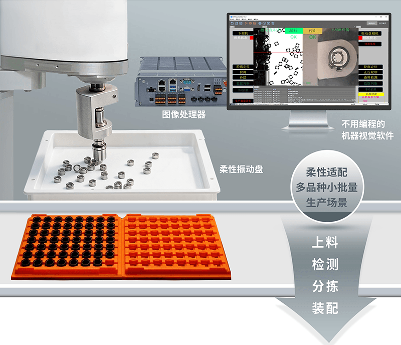
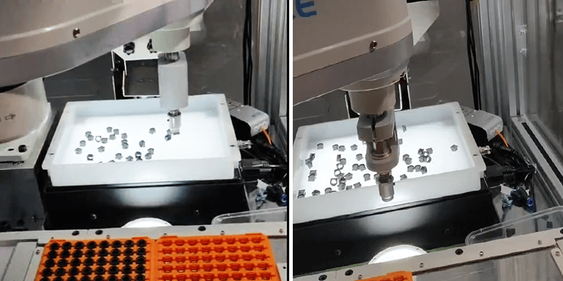
A complete Flexible Vibrating Disk vision system usually consists of the following hardware layers: vibration drive layer (excitation controller + vibration platform), imaging layer (industrial camera + strobe light source + lens/diffuser plate), processing layer (CKVision Image Processor) and execution layer (six-axis collaborative robot or SCARA robot + end effector). CKVision Image Processor is located between the imaging layer and the execution layer, serving as the data convergence and decision node of the entire system.
In terms of physical connection, the camera is connected to the processor via GigE or USB3, the strobe control signal is directly driven by the digital I/O of the processor, bidirectional data exchange (delay less than 1ms) is realized between the vibration controller and the processor via EtherCAT real-time bus, and the robot receives pick-up coordinate instructions via TCP/IP or EtherCAT. The entire system performs timing synchronization through a unified time reference (IEEE 1588 PTP protocol), ensuring microsecond-level alignment of all devices.
4.2 Software Interface and Data Flow
CKVision Image Processor provides an open API based on CkvisionSDK, allowing upper-layer systems (MES, SCADA or robot teach pendant) to query real-time detection results, modify vision parameters or trigger model switching via standard Ethernet. For changeover scenarios, operators only need to select the vision recipe corresponding to the part on the HMI interface, and the processor can complete model loading and parameter switching within 2~5 seconds. Cooperating with one-click switching of excitation recipes of the vibration controller, the whole line achieves fast changeover in less than 10 minutes.
The data flow closed loop is as follows: image acquisition → preprocessing (denoising, enhancement) → target detection and pose estimation → multi-target tracking → priority sorting → coordinate output (robot) + correction instruction (vibration controller) → next frame acquisition trigger. The entire loop can be completed within 20~40ms under optimal conditions, supporting high-speed beats of 60~120 pick-ups per minute.
5. Analysis of Typical Application Cases
5.1 Case 1: Automatic Screw Feeding System for 3C Electronics
A consumer electronics ODM manufacturer deployed a Flexible Vibrating Disk-based screw feeding system on smartphone assembly lines, which needs to be compatible with mixed-line feeding of 8 specifications of screws from M1.0 to M2.5. Previously, when using traditional vibrating feeders, changeover required replacing the entire set of bowls, taking about 45 minutes, and the inventory of bowls for different specifications occupied a lot of storage space.
After introducing CKVision Image Processor, the system trained independent deep learning recognition models for 8 types of screws and managed them in the form of recipes in the processor. The vision system can distinguish different specifications of screws with 99.7% accuracy under mixed material conditions, and judge their upright (head up) or inverted status. For screws with incorrect poses, the vibration controller receives correction instructions and flips them to the correct orientation through local excitation. Finally, the system reduced the changeover time to 8 minutes, increased the overall equipment effectiveness (OEE) of the production line by about 18%, and reduced the defect rate of missing/misplaced screws to below 5 parts per million.
5.2 Case 2: Mixed Material Sorting of Automotive Fasteners
A first-tier automotive supplier faced the flexible feeding demand for multi-variety and small-batch fasteners (32 types in total, including bolts, nuts, washers and circlips) in the engine assembly workshop. The materials cover galvanized steel, stainless steel and engineering plastics, with significant differences in reflective characteristics, bringing great difficulties to traditional optical solutions.
The engineering team customized a coaxial light + ring diffused light dual-light source solution for the project, cooperating with the adaptive lighting selection function of CKVision Image Processor: the system automatically performs one adaptive lighting calibration when each batch of new materials is launched, evaluates the image quality score under different light source combinations, selects the optimal light source configuration and stores it in the corresponding recipe. This mechanism fully automates the manual light adjustment between different materials, shortening the commissioning cycle from about 2 hours per new material to less than 15 minutes. After system deployment, the overall recognition accuracy of 32 types of fasteners reaches 99.4%, with more than 3600 pick-ups per hour, meeting the beat requirements of engine assembly lines.
5.3 Case 3: Precision Feeding of Medical Consumables
The medical device industry has much higher requirements for cleanliness and precision of part feeding than general industrial scenarios. A syringe component manufacturer needs to supply transparent plastic sealing gaskets with a diameter of 3mm to the assembly robot in a specific orientation (convex surface up). The part is made of transparent TPE, which is almost indistinguishable from the background under ordinary white light.
The solution adopts CKVision Image Processor with a deep red backlight panel (660nm wavelength) for backlight imaging, forming a high-contrast contour image by using the refractive index difference between the part and the background, and then distinguishing the two orientations with or without convex platforms through a precise circular contour fitting algorithm. Finally, the system runs stably in a Class 100,000 clean room, with a single orientation judgment accuracy of ±2°, zero outflow of defective products (parts with wrong orientation), meeting the data traceability requirements of FDA 21 CFR Part 11.
6. Quantitative Benefit Comparison
Based on the data of multiple implemented projects, the in-depth integration solution of Flexible Vibrating Disk and CKVision Image Processor shows significant advantages over the traditional rigid vibrating feeder solution in the following key indicators:
| Comparison Indicators |
Traditional Rigid Vibrating Feeder |
Flexible Disk + CKVision |
| Changeover Time |
30~90 minutes |
5~10 minutes (over 80% reduction) |
| Compatible Material Types |
Single fixed (one bowl one material) |
More than 50 types (software recipe switching) |
| Feeding Positioning Accuracy |
±0.5~1.0mm (mechanical constraint) |
±0.05~0.15mm (vision guidance) |
| Orientation Recognition Accuracy |
About 95% (mechanical filtering) |
99.4~99.7% (AI recognition) |
| Changeover Labor Cost |
Requires professional commissioning engineers |
One-click switching by operators |
| OEE Improvement Range |
Benchmark |
Increased by 15~25% |
| Equipment Floor Space |
Storage space for multiple sets of bowls |
Saves about 60% of storage space |
| New Product Introduction Cycle |
4~8 weeks (customized bowls) |
3~5 days (vision model training) |
7. Key Points of Project Implementation and Common Misunderstandings
7.1 Lighting Design Is the Key to Success
In Flexible Vibrating Disk vision systems, the importance of lighting design is often underestimated. A correct lighting solution should form sufficient grayscale contrast between part contours, key features and the background, while suppressing saturated light spots caused by specular reflection. The recommended selection process in engineering practice is: first determine the key recognition features of parts (contour shape, surface protrusions, color marks, etc.), then select the light source type (backlight / coaxial / ring diffused / strip side light) according to the feature type, and finally verify the robustness under different batches of materials and ambient light conditions through experiments.
7.2 The Quality of Sample Data Determines the Model Upper Limit
In the deep learning model training stage, the root cause of failure in many projects is insufficient coverage of training data. An ideal training set should include: samples under various lighting conditions, samples with appearance differences between new and old batches of materials, samples with slight wear or contamination that may occur during production, and negative samples (similar but non-target parts). It is recommended to collect at least 500 annotated images for each material type, and continuously collect online data for incremental model updates in the first two weeks after production.
7.3 Collaborative Commissioning of Vibration Parameters and Vision Parameters
There is a strong coupling relationship between the excitation parameters (frequency, amplitude, phase) of Flexible Vibrating Disk and the exposure parameters (exposure time, strobe trigger phase) of the vision system. Wrong parameter combinations will cause image blur or part movement speed exceeding the processing capacity of the tracking algorithm. The recommended commissioning sequence is: first fix the vibration parameters to adjust the vision to clear imaging, then optimize the vibration strategy to improve part flipping efficiency under fixed vision parameters, and finally perform joint iterative optimization.
7.4 System Maintenance and Continuous Optimization Mechanism
A regular maintenance system needs to be established after the system is launched: clean the camera lens and diffuser plate monthly, check the brightness attenuation of strobe lights (general service life is 50,000~100,000 hours), and re-evaluate the recognition accuracy of the model on the latest batches of materials quarterly. It is recommended to enable automatic archiving of low-confidence samples in the data recording function of CKVision Image Processor, automatically save images with recognition confidence below the threshold as candidate samples for the next round of model updates, forming a benign closed loop of system self-evolution.
8. Future Development Trends
Looking ahead, the integration of Flexible Vibrating Disk and image processor will be deepened along three main paths.
First, the introduction of 3D vision. The current mainstream solutions still focus on 2D planar vision, but with the continuous cost reduction of structured light and Time-of-Flight (ToF) cameras, 3D vision will gradually enter Flexible Vibrating Disk systems, enabling the system to handle the 3D poses of irregular curved parts (such as rubber seals, flexible cables) and realize more complex pick-up guidance.
Second, reinforcement learning-driven adaptive vibration strategies. Current vibration control strategies are mostly pre-designed fixed programs. In the future, reinforcement learning algorithms will be introduced, allowing the system to independently explore and optimize excitation parameter combinations according to the part motion status fed back by vision, realizing rapid self-learning for new material types and further shortening the new product introduction cycle.
Third, cloud collaboration and knowledge sharing. With the help of industrial Internet platforms, vision models and vibration recipes of multiple production lines within the same enterprise can be centrally managed and shared. When introducing new production lines, similar recipes in the existing knowledge base can be directly used as a starting point, combined with a small amount of local calibration data for rapid migration, greatly reducing the commissioning cost and time investment of each new production line.
9. Conclusion
Flexible Vibrating Disk represents a fundamental transformation of workpiece feeding technology from “mechanical constraints” to “visual perception”, while CKVision Image Processor has become the core enabling technology for this transformation with its high-performance hardware architecture, complete vision algorithm system and open integration interface. Their in-depth cooperation is not just a simple combination of hardware, but the construction of a complete “perception-decision-control” closed-loop intelligent system.
Practical application data in various industries, from 3C electronics to automotive manufacturing, from medical consumables to daily chemical packaging, have proven that this combined solution can bring quantifiable and significant improvements in multiple dimensions such as changeover efficiency, recognition accuracy, production line flexibility and quality control. With the continuous evolution of 3D vision, reinforcement learning and industrial Internet technologies, the collaborative capability of Flexible Vibrating Disk and intelligent image processors will further break through existing boundaries and release the core value of smart manufacturing in a wider range of application scenarios.
For manufacturing enterprises planning flexible production line upgrades, now is the best time to evaluate and introduce this advanced solution—the technology is mature, cases have been verified, and the ecosystem is complete.