

1. Project Requirements
Precision Parameters
- Wafer circuit width: 0.005mm, cutting blade width: 0.003mm
- Vision positioning accuracy for cutting: ±0.001mm
- Post-cut kerf inspection tolerance: ±0.0005mm
Host Software Integration Requirements
The client independently develops the dicing machine host program, requiring image processing interfaces for dual imaging systems (low-magnification telecentric & high-magnification microscope) to realize 7 core functions:
- Real-time dual-camera image display on host software, auto image saving to designated folders;
- Auxiliary auto-focus for both imaging systems;
- Image calculation via low-magnification telecentric camera to guide platform horizontal correction;
- Fit cutting centerline from high-magnification images, calculate deviation from horizontal reference boundary;
- Inspect cut kerf to judge whether lines exceed tolerance range;
- Multi-spec wafer template learning & storage, one-click template loading for product switching;
- Auto extract centerline coordinates, mark upper/lower boundaries on images for cutting guidance.
Deliver complete VS2012 VB.NET Demo program, full debugging support and technical assistance throughout integration.
2. CKVision Overall Solution
2.1 Hardware Standards
- Motion Mechanism: Platform flatness & motor positioning accuracy shall be better than 1/2 of overall machine tolerance; ultra-low mechanical jitter to guarantee micron-level positioning; clarify production CT cycle for camera model selection.
- Dual-Camera Hierarchical Positioning: Camera 1 for rough positioning, Camera 2 for precise positioning; capture images at left & right positions to fit reference lines, output coordinates & rotation angle to guide cutting. Horizontal & vertical cutting only require 90° tray rotation to reuse positioning logic.
- Camera Recommendation: Global shutter small-format industrial cameras, high-speed trigger for on-the-fly capture, short focal lens to ensure sufficient depth of field.
2.2 Secondary Development via OCX Control(CKVision APP)
Adopt embedded development with CKVisionCtrl.ocx(CKVision APP), compatible with VB.NET, C#, C++ and other host development platforms:
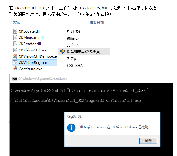
- One-click control registration via batch script, complete Demo project provided;
- 9-point calibration algorithm with Mark point to convert pixel coordinates to physical mechanical coordinates;
- Coordinate linkage: Vision reads mechanical coordinates at image capture moment to calculate actual wafer position;
- Dual-line fitting positioning: Capture images at left/right FOV, fit two reference lines to generate center baseline & rotation compensation angle.
3. Core Vision Function Introduction
3.1 CKVision APP Control Integration Steps
- Run CKVisionReg.bat with administrator privileges to register control;
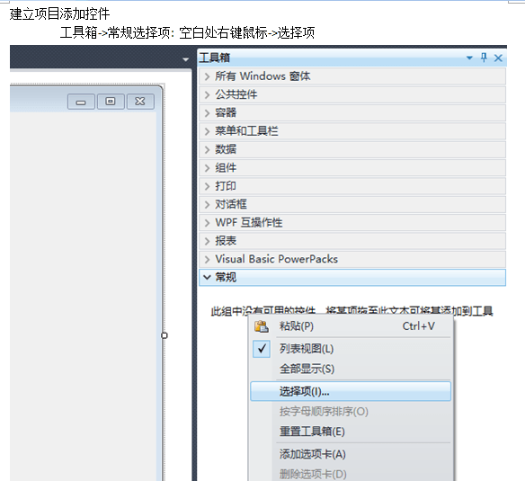
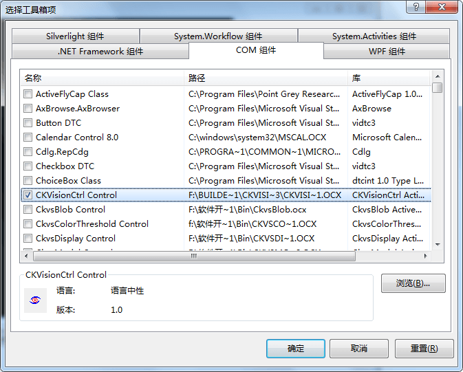
- Tick CKVisionCtrl Control in VS Toolbox COM components, drag to form for quick integration;
- Built-in functions: view zoom, view lock, project configuration loading, ready for direct invocation.
3.2 Core Image Algorithms
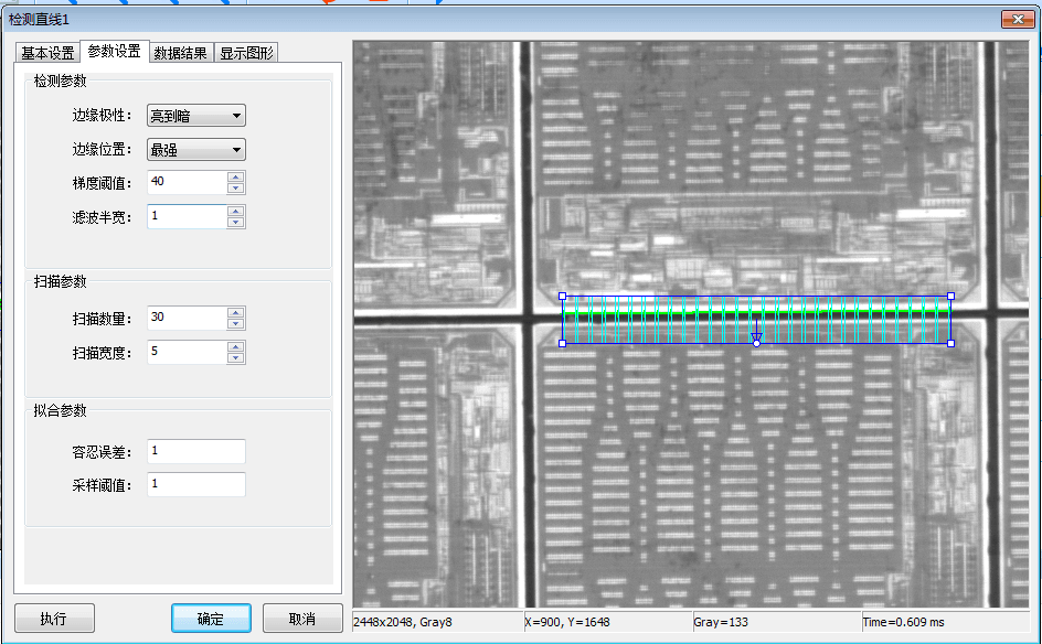
- Multi-point line fitting: Collect dozens of edge scan points to fit upper/lower cutting boundaries, output center coordinates & tilt angle accurately;
- Image preprocessing: Filter denoising, gradient threshold adjustment to eliminate wafer texture interference for clear, stable edges;
- Shape template matching: Output matching X/Y coordinates & rotation angle to motion platform for automatic correction;
- Kerf deviation inspection: Compare with standard centerline, auto trigger NG signal when kerf exceeds tolerance.
3.3 Full Equipment Workflow
- Rough Positioning: Camera 1 captures left & right images, fits reference lines, calculates wafer center & rotation angle for tray auto correction;
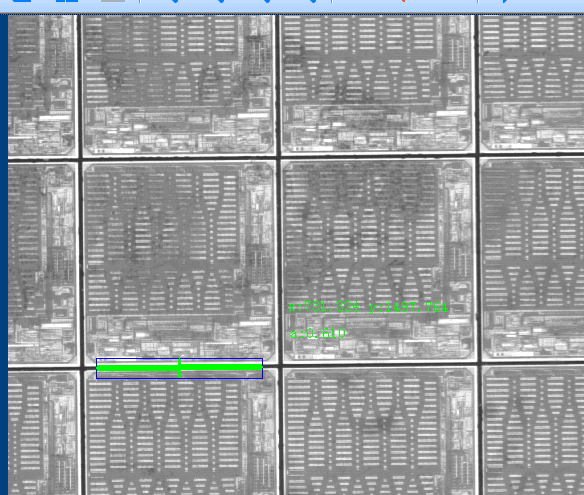
- Precise Positioning: High-magnification camera re-captures dual-side images to fit ultra-precise centerline;
- Cutting Execution: Vision transmits coordinate data to blade for cutting; horizontal/vertical switching only needs 90° tray rotation.
4. Matching Requirements for Host & Mechanism
- Stable imaging with clear edge separation; image fluctuation ≤ 1/3 of vision tolerance;
- Extremely low mechanical vibration to avoid micron-level positioning offset;
- Global shutter high-speed camera to support on-the-fly capture and production cycle demands.
5. Full Technical Support Service
- Free sample lighting test & professional vision solution report;
- On-site software demonstration, hardware model matching & selection;
- Graphic programming training for client engineers;
- Full assistance for host software joint debugging & stable mass production launch;
- Emergency on-site technical support.
6. Solution Advantages
- Independently developed CKVision algorithm, complete IP rights including software copyrights & invention patents;
- Lightweight CKVision APP control, drastically shorten host software development cycle without complex vision coding;
- Hierarchical rough & precise positioning architecture, achieve ±0.001mm ultra-high accuracy for strict semiconductor wafer processes;
- Multi-protocol communication support: TCP/IP, IO, RS232, compatible with PLC, motion controllers & robots;
- Multi-spec wafer template storage, quick product switching for flexible production lines.